DC - Generator
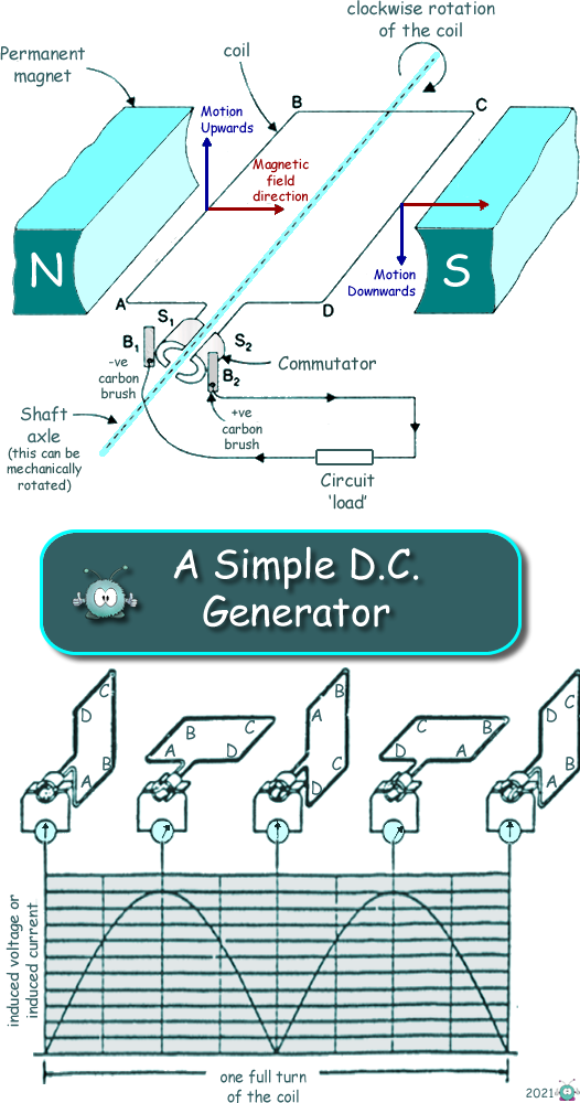
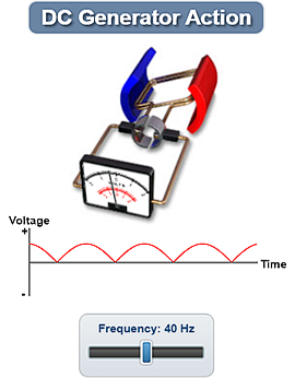
A DC generator is a device which converts mechanical energy into electrical energy in the form of a DC supply. You do not get a steady voltage - like you get from a battery, but it is still DC as it only makes current flow in one direction - one terminal is constantly positive with respect to the other one. (See AC/DC)
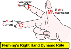
The DC generator has split ring commutator (like the motor) instead of the 'slip rings' found in the AC Generator. The split ring commutator consists of two semi-cylindrical brass rings (see S1 and S2 on the diagram - the split between them is much tinier that on the diagram!). These are rigidly attached to the two ends of the coil. As the coil rotates, the two split rings also rotate about the same axis of rotation. The carbon brushes (B1 and B2) are fixed to a housing that also has terminal fixed to it. This allows the wires for the external circuit to be connected to the generator. (In the diagram a load resistor is placed in the external circuit). The carbon brushes are not like 'brushes' you may use for your hair or to clean with... they are called brushes because they 'brush' the shaft axle as it turns. They are carbon blocks that are usually pushed against the commutator with a spring or something similar to ensure good contact - as they are put to use they 'wear out' and need replacing. Carbon is a conductor (although a 'poor' one) that makes good low friction contact - working well in this task. Using Fleming's Right Hand RuleThe direction of the induced voltage (and therefore current flow) can be determined from Fleming's Right Hand rule.
Here is an interactive Java applet for you to look at:
|
Follow me...
|


 The sinusoidal output is often 'smoothed' using a


