
 |
Diffraction Gratings Reflection Diffraction Gratings(not on the syllabus!) Transmission Diffraction GratingsA transmission diffraction grating is a slide with large number of parallel, closely spaced slits (transparent spaces) drawn on it. Early ones were carbon covered glass slides etched by a needle point - now they tend to be printed onto a slide.
When a parallel beam of monochromatic light is directed normally (at right angles to it!) at a diffraction grating, light is transmitted by the grating in certain directions only. This is because:
It is excellent at separating the colors in incident light because different wavelengths are diffracted at different angles, according to the grating relationship:
d sin θ = nλ where
The separation being so small makes the angle large. Consider a magnified view of part of a diffraction grating:
Each slit diffracts the light waves that pass through it. The diffracted waves then interfere with each other. Where crests meet or troughs meet there is reinforcement (constructive interference) – where a crest and tough meet there is cancellation (destructive interference). This results in only the ‘orders’ of light being viewed. As each diffracted wavefront emerges from a slit, it reinforces a wavefront from each of the adjacent slits. For example, in the diagram, the wavefront emerging at P reinforces the wavefront emitted from Q one cycle earlier, which reinforces the wavefront emitted from R one cycle earlier, etc. The effect is to form a new wavefront PYZ which travels in a certain direction and contributes to the first order diffracted beam. The diagram above shows the formation of a wavefront of the nth order beam. The wavefront emerging from slit P reinforces a wavefront emitted n cycles earlier by the adjacent slit Q. This earlier wavefront therefore must have travelled a distance of n wavelengths from the slit. Therefore the perpendicular distance QY from the slit to the wavefront is equal to nλ , where λ is the wavelength of the light waves. Since the angle of diffraction of the beam, θ , is equal to the angle between the wavefront and the plane of the slits, it follows that sin θ = QY/QI where QP is the grating spacing (i.e. the centre-to-centre distance d between adjacent slits). Substituting d for QP and nd for QY therefore gives sin θ = nλ /d. Rearranging this equation gives the diffraction grating equation for the angle of diffraction of the nth order beam dsin θ = n λ
The maximum number of orders is given by the value of d/λ, rounded down to the nearest whole number. ----------------------------------------------- The diffraction grating is an immensely useful tool for the separation of the spectral lines associated with atomic transitions. It separates the different colors of light much more than the dispersion effect in a prism is able to - it uses diffraction not refraction to do it!
The condition for maximum intensity is the same as that for the double slit or multiple slits, but with a large number of slits the intensity maximum is very sharp and narrow, providing the high resolution for spectroscopic applications. The peak intensities are also much higher for the grating than for the double slit.
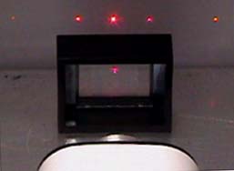
When monochromatic light (light of a single wavelength - like the 632.8 nm red light from a helium-neon laser) strikes a diffraction grating it is diffracted to each side in multiple orders. The condition for maximum intensity is the same as that for a double slit. However, angular separation of the maxima is generally much greater because the slit spacing is so small for a diffraction grating.
Questions
|
Follow me...
|
 See here for a
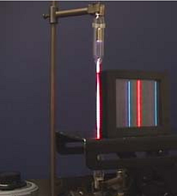


Cyberphysics - a web-based teaching aid - for students of physics, their teachers and parents....