
 |
|
||||||||||
 sing an oscilloscope

 |
|
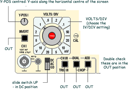
VOLTS/DIV |
TIME/DIV |
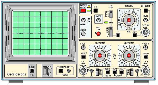
 Switch ON, red button, top centre:

The green LED illuminates and, after a few moments, you should see a small bright spot, or trace, moving fairly slowly across the screen.
Find the Y-POS 1
control:

What happens when you 'twiddle' this?
The Y-POS 1 allows you to move the spot up and down the screen. For the present, adjust the trace so that it runs horizontally across the centre of the screen.
Now investigate the
INTENSITY and FOCUS controls:

When these are correctly set, the spot will be reasonably bright but not glaring, and as sharply focused as possible. (The TR control is screwdriver adjusted. It is only needed if the spot moves at an angle rather than horizontally across the screen with no signal connected.)
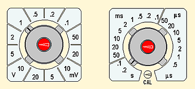
The TIME/DIV control
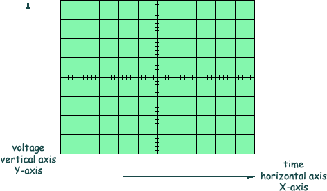
determines the horizontal scale of the graph which appears on the oscilloscope
screen.
With 10 squares across the screen and the spot moving at 0.2 s/DIV, how long does it take for the spot to cross the screen? The answer is 0.2 x 10 = 2 s. Count seconds. Does the spot take 2 seconds to cross the screen?
Now rotate the TIME/DIV control clockwise:
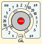
With the spot moving at 0.1 s/DIV, it will take 1 second to cross the screen.
Continue to rotate TIME/DIV clockwise. With each new setting, the spot moves faster. At around 10 ms/DIV, the spot is no longer separately visible. Instead, there is a bright line across the screen. This happens because the screen remains bright for a short time after the spot has passed, an effect which is known as the persistence of the screen. It is useful to think of the spot as still there, just moving too fast to be seen.
Keep rotating TIME/DIV. At faster settings, the line becomes fainter because the spot is moving very quickly indeed. At a setting of 10 µs/DIV how long does it take for the spot to cross the screen?
The VOLTS/DIV controls determine the vertical scale
of the graph drawn on the oscilloscope screen.
Check that VOLTS/DIV is set at 1V/DIV and that the adjacent controls are set correctly:
The Hameg HM 203-6 has a built in source of signals which allow you to check that the oscilloscope is working properly.
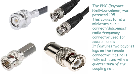
A connection to the input of channel 1, CH 1, of the oscilloscope can be made using a a BNC plug (see aboove), as shown below:
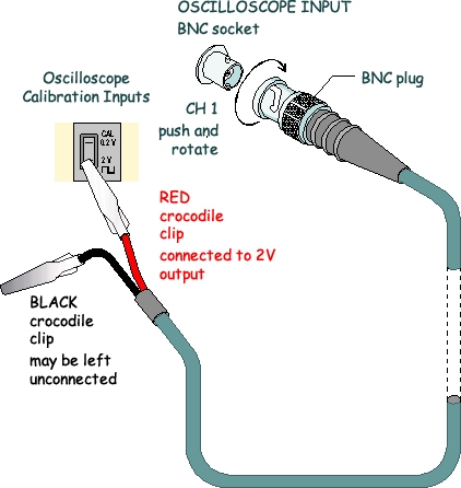
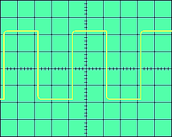
The diagram above shows a special lead that has a BNC plug at one end and crocodile clips at the other - it is called a 'test lead' or a 'BNC plug-alligator lead'. When the crocodile clip from the red wire is clipped to the lower metal terminal, a 2 V square wave is connected to the input of CH 1.
Adjust VOLTS/DIV and TIME/DIV until you obtain a clear picture of the 2 V signal, which should look like this:
What do these Y-POS 1 and X-POS controls do?
 |
 |
 |
 |
Y-POS 1 moves the whole trace vertically up and down on the screen, while X-POS moves the whole trace from side to side on the screen.
These control are useful because the trace can be moved so that more of the picture appears on the screen, or to make measurements easier using the grid which covers the screen.
You have now learned about and used the most important controls on the oscilloscope.
![]() You know that the function of an oscilloscope is to draw a
V/t graph.
You know that the function of an oscilloscope is to draw a
V/t graph.
![]() You know how to put all the controls into their
'normal' positions, so that a trace should appear when the oscilloscope is
switched on.
You know how to put all the controls into their
'normal' positions, so that a trace should appear when the oscilloscope is
switched on.
![]() You know how the change the horizontal scale of the V/t graph, how to change the vertical scale, and how to
connect and display a signal.
You know how the change the horizontal scale of the V/t graph, how to change the vertical scale, and how to
connect and display a signal.
![]() What is needed now is practice so that all of these controls become
familiar!
What is needed now is practice so that all of these controls become
familiar!


Follow me...
![]()
![]()


Cyberphysics - a web-based teaching aid - for students of physics, their teachers and parents....