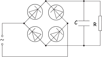
Capacitor Questions

Q9. A sinusoidal alternating voltage supply is connected to a bridge rectifier consisting of four ideal diodes. The output of the rectifier is connected to a resistor R and a capacitor C as shown in the diagram.

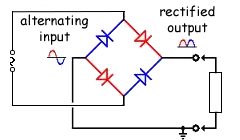
A rectifier circuit allows current to only flow in one direction.

Both halves of the cycle have current flow in the same direction.

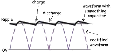
The function of C is to provide some smoothing to the potential difference across R.

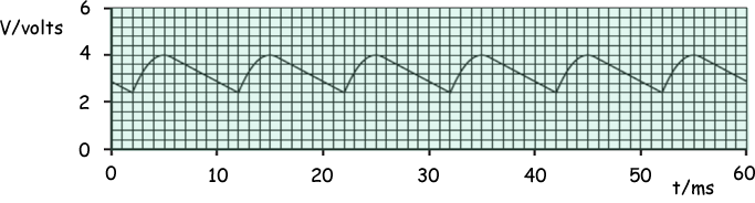
The variation with time t of the potential difference V across the resistor R is shown in the graph below.


(a) Use the graph to determine, for the alternating supply,

(i) the peak voltage

V0 = 4 volts

(1 mark)

(ii) the root-mean-square (r.m.s.) voltage

VRMS= V0 / √2

VRMS= 2.8 volts

(1 mark)

(iii) the frequency

The frequency of the rectified signal is double that of the original alternating one.

Tsupply = 22 - 2 (see graph) = 20 ms

f = 1/(20 x 10-3)

f = 50 Hz

(2 marks)

(b) The capacitor C has capacitance 5.0 μF. For a single discharge of the capacitor through the resistor R, use the graph to

(i) determine the change in potential difference

ΔV = 4.0 - 2.4 (see graph) = 1.6V

(1 mark)

(ii) determine the change in charge on each plate of the capacitor,

ΔQ = CΔV

ΔQ = 5.0 x 10-6 x 1.6

ΔQ = 8.0 x 10⁻⁶ C

(2 marks)

(iii) show that the average current in the resistor is 1.1 × 10⁻³ A.

I = ΔQ /t

t = 7.0 x 10⁻³s (see graph)

I = (8.0 x 10⁻⁶)/(7.0 x 10-3)

I = 1.1 × 10⁻³ A Q.E.D.


(2 marks)

(c) Use the graph and the value of the current given in (b)(iii) to estimate the resistance of resistor R.

Average current = 1.1 × 10⁻³ A

We therefore have to find the average voltage

(from the graph - midpoint between 4.0 and 2.4 = 2.4 + 1.6/2 = 2.4 + 0.8 = 3.2)

Average voltage = 3.2V

We can then relate similar voltage and current to determine resistance using Ohm's equation

V = IR

R = V/I = 3.2/ 1.1 × 10⁻³

R = 2900 Ω

(2 marks)

(Total 11 marks)