'A' Level Questions - The Oscilloscope
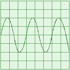
Q1. The diagram shows a trace on the screen of an oscilloscope. The Y-sensitivity of the oscilloscope is set at 5.0 V per division and the time base is set at 0.50 ms per division.

(a) For the trace, determine
(i) the maximum positive value of potential difference,
(ii) the maximum negative value of potential difference,
(iii) the frequency of the signal.
(4 marks)
(b) The trace shows the variation in the potential difference across a 100  resistor. Calculate the energy dissipated in the resistor
(i) for the first 1.00 ms,
(ii) between 1.00 ms and 1.50 ms,
(iii) in one cycle,
(iv) in one second.
(5 marks)
(Total 9 marks)

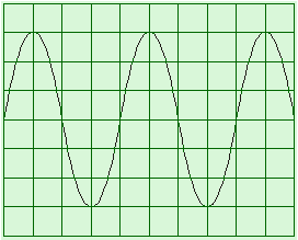
Q2. An alternating current (a.c.) source is connected to a resistor to form a complete circuit. The trace obtained on an oscilloscope connected across the resistor is shown below. The oscilloscope settings are: Y sensitivity 4.0V per division, time base 1.0 ms per division.
(a) Determine the peak voltage of the a.c. source.
(b) Hence calculate the r.m.s. voltage.
(c) Determine the time period of the a.c. signal.
(d) Hence calculate the frequency of the a.c. signal.
(Total 4 marks)
Q3. A cathode ray oscilloscope is used to study the waveform of a sinusoidal alternating voltage of frequency 100 Hz and peak voltage 2.0 V. If the time base is set to 2.0 ms div–1 and the voltage sensitivity is 0.5 V div–1, draw, in the grid below, the trace you would expect to see on the screen.

(Total 4 marks)
Q4.

(a) The circuit shown in the diagram on the left of the above, may be used to determine the internal resistance of a battery. An oscilloscope is connected across the battery as shown. The diagram on the right (above) represents the screen of the oscilloscope.
The time base of the oscilloscope is switched off throughout the experiment. Initially the switches S1 and S2 are both open. Under these conditions the spot on the oscilloscope screen is at A.
(i) Switch S1 is now closed, with S2 remaining open. The spot moves to B. State what the deflection AB represents.
(ii) Switch S1 is kept closed and S2 is also closed. The spot moves to C. State what the deflection AC represents.
(iii) The vertical sensitivity of the oscilloscope is 0.50 V div–1. Calculate the current through the 14 resistor with both switches closed.
(iv) Hence, calculate the internal resistance of the battery.
(6 marks)
(b) The oscilloscope is now connected to an alternating voltage source of rms value 3.5 V.
(i) Calculate the peak value of the alternating voltage.
(ii) Draw on the diagram below what you would expect to see on the oscilloscope screen, if the time base is still switched off and the voltage sensitivity is altered to 2.0 V div–1.

(3 marks)
(Total 9 marks)
Q5. The circuit below shows a sinusoidal ac source connected to two resistors, R1 and R2, which form a potential divider. Oscilloscope 1 is connected across the source and oscilloscope 2 is connected across R2.
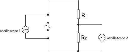
(a) The diagram below shows the trace obtained on the screen of oscilloscope 1. The time base of the oscilloscope is set at 10 ms per division and the voltage sensitivity at 15 V per division.
For the ac source, calculate
(i) the frequency,
(ii) the rms voltage.
(4 marks)
(b) The resistors have the following values: R1 = 450 and R2 = 90 . Calculate:
(i) the rms current in the circuit,
(ii) the rms voltage across R2.
(2 marks)
(c) Oscilloscope 2 is used to check the calculated value of the voltage across R2. The screen of oscilloscope 2 is identical to that of oscilloscope 1 and both are set to the same time base.
Oscilloscope 2 has the following range for voltage sensitivity: 1 V per div., 5 V per div., 10 V per div. and 15 V per div.
State which voltage sensitivity would give the most suitable trace. Explain the reasons for your choice.
(3 marks)
(Total 9 marks)