GCSE Standard Questions: Electric Circuits
Q4. The diagram shows the inside of a battery pack designed to hold three identical 1.5 V cells.

(a) Tick the one of the arrangements below that would give a 4.5 V output across the battery pack terminals T.

[1 mark]
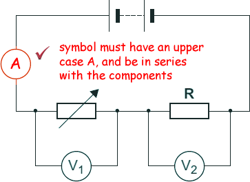
(b) The following diagram shows a variable resistor and a fixed value resistor connected in series in a
circuit.

Complete the diagram above to show how an ammeter would be connected to measure the current through the circuit. Use the correct circuit symbol for an ammeter.
[1 mark]
(c) The variable resistor can be adjusted to have any value from 200Ω to 600Ω .
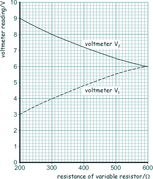
The following graph shows how the reading on voltmeter V1 and the reading on voltmeter V2 change as the resistance of the variable resistor changes.

(i) Calculate the potential difference of the battery from the graph and explain how you did it.
The pd of battery is shared between the variable resistor and fixed resistor - it is therefore the sum of the two voltmeter readings for any value of the resistance of the variable resistor  - for example:
pd of battery = 9V + 3V = 12V when Rvariable = 200Ω
pd of battery = 8V + 4V = 12V when Rvariable = 300Ω
pd of battery = 6V + 6V = 12V when Rvariable = 600Ω
pd of battery is therefore 12V 
[2 marks]
(ii) Now determine the resistance of the fixed resistor, R using the graph and explain how you did it.
The potential drop across two resistors is related to the size of their comparative resistance - therefore when they are of equal resistance they will share the voltage equally.
When Rvariable = 600Ω it gets half the pd of the battery
- therefore the fixed resistance R has a value of 600Ω
[2 marks]
(iii) Calculate the current through the circuit when the resistance of the variable resistor equals 200 Ω.
Total resistance = Rvariable + R
RTOTAL = 200 Ω + 600 Ω
RTOTAL = 800 Ω 
V = IR
I = V/R
I = 12/800 
I = 0.015 A 
[3 marks]
(Total 9 marks)


