Resistivity Question
Q2.
(a) A student wishes to measure the resistivity of the material of a uniform resistance wire. The available apparatus includes a battery, a switch, a variable resistor, an ammeter and a voltmeter.
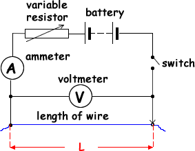
(i) Draw a circuit diagram which incorporates some or all of this apparatus and which enables the student to determine the resistivity of the material.
circuit diagram to show:
wire, ammeter, battery, (variable resistor) and switch in series  and a voltmeter in parallel with the wire
(ii) State the measurements which must be made to ensure that a reliable value of the resistivity is obtained.
Method 1: constant length of wire
- measure length (of wire) with a metre rule
- measure diameter (of wire) with a micrometer screwguage(This should be done in about three places on the wire at different orienations).
- vary the resistor to obtain different voltage and current and then measure voltage across the wire with a voltmeter and the current through the wire with an ammeter
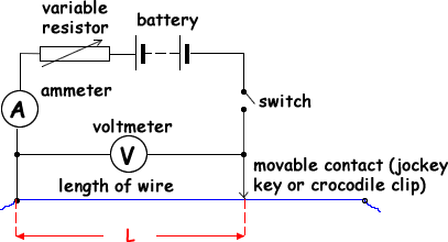
Method 2: variable length of wire
- measure diameter (of the wire) with a micrometer screwguage(This should be done in about three places on the wire at different orienations).
- vary the length of the wire
- measure length (each time you change it) with a metre rule
- measure voltage across the wire with a voltmeter and the current through the wire with an ammeter
(iii) Explain how a value of the resistivity would be obtained from the measurements.
R = ρ L/A
Varying L Method
If we reaarange the equation we get R = ((ρ/A) L.
This equation can be compared to Y = mx + c (the equation of a straight line). By plotting R on the Y axis and L on the x-axis we can obtain a straight line graph. The graph will go through the origin and the gradient of the graph will be the resistivity of the wire divided by the cross sectional area.
The diameter dhaving been measured we can calculate the cross sectional area aa A = πd2/4
We can then determine the resistivity by multiplying the gradient by the cross sectional area.
Constant L Method
Plot a graph of V against I to determine the average value for the resistance of the wire from the gradient.
The diameter dhaving been measured we can calculate the cross sectional area aa A = πd2/4
If we reaarange the equation we get ρ= RA/L and by substituting the values measured and calculated into it we can find the resistivity of the wire.
(10 marks)
(b) A wire made from tin with cross-sectional area 7.8 × 10⁻⁹ m2, has a pd of 2.0 V across it. Calculate the minimum length of wire needed so that the current through it does not exceed 4.0 A.
The resistivity of tin is 1.1 × 10⁻⁷ Ω m
For the current not to exceed 4.0 A the resistance must be no less than
V = IR so R = V/I = 2.0/4.0 = 0.5Ω
R = ρ L/A
L = AR/ρ = 7.8 × 10–9 x 0.5 / 1.1 × 10⁻⁷
L = 0.03545
L = 0.036 m
(2 marks)
(Total 12 marks)