Practical electricity experiment questions
Q3. This question is about an experiment to determine the internal resistance of a power supply.
(a) Lex is given the circuit and the four resistors of known resistance shown in this diagram:
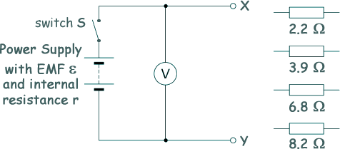
He can change the external resistance R of the circuit between terminals X and Y.
This is done by connecting different combinations of two resistors in series or in parallel between X and Y.
This method can produce 12 different values for R.
(i) Calculate the largest value of R that Lex can obtain using two resistors.
In series (largest values)
RTOTAL = R1 + R2
RTOTAL = 8.2 + 6.8
RTOTAL = 15 Ω 
[1 mark]
(ii) Calculate the smallest value of R that the student can obtain using two resistors.
In parallel (smallest values)
1/RTOTAL = 1/R1 + 1/R2
1/RTOTAL = 1/2.2 + 1/3.9
1/RTOTAL = 0.711
RTOTAL = 1.4 Ω
[2 marks]
(iii) With switch S closed (in the on position) and no resistors connected between X and Y the voltmeter reading V is 1.62 V.
Lex concludes that this voltmeter reading equals the emf ε of the power supply.
State why the his conclusion that ε = 1.62 V was correct.
The power supply is on open circuit (with only a very tiny current flow through the voltmeter).
OR
Current flow is negligible as the voltmeter has a very large resistance.
OR
There is no external circuit current load, so no lost volts.
[1 mark]
(b) This diagram shows one particular combination and arrangement of two resistors that Lex could use.
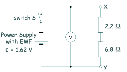
When S is closed the voltmeter reading V is 1.14 V.
(i) Explain why V is less than 1.62 V when S is closed.
Current through power supply leads to some of the emf from the supply to be used across the internal resistance, and total voltage is shared between the internal and external resistances according to their values.
[1 mark]
(ii) It can be shown that
ε - V = r x V/R
where r is the internal resistance of the power supply.
Determine (ε – V ) and V/R for this circuit.
(ε – V ) = 1.62 - 1.14
(ε – V ) = 0.48 volts
V/R = 1.14/(6.8 + 2.2)
V/R = 1.14/9.0
V/R = 0.13 VΩ-1
[1 mark]
(iii) Lex obtains values of V for five further different values of R.
These data were used to produce this graph of (ε – V ) against V/R

Plot the point you determined in b(ii) on the graph and add a suitable best-fit line.
[1 mark]
(iv) Use the graph to determine a value for r.
r is the gradient of the graph
Δy/Δx = AB/BC
AB/BC = (1.145 - 0.4)/(0.30 - 0.105)
AB/BC =0.745/0.195
AB/BC = 3.8 Ω
[2 marks]
(c) Here is a different method for varying the resistance R - instead of using four individual resistors Lex could use four resistors connected in a loop with sockets A, B, C and D at each junction. Two leads are used to connect the resistor loop to X and Y.
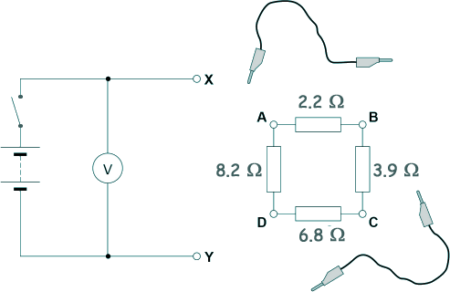
Discuss whether this method is an improvement over the method described in question.
In your answer, you should refer to the number of different values that can be obtained for R.
The individual resistor method is better because more R values are obtainable. Only six values of R are possible when using the quadrangle of resistors, whereas you can make up twelve by using four individual ones.
[2 marks]
(Total 11 marks)