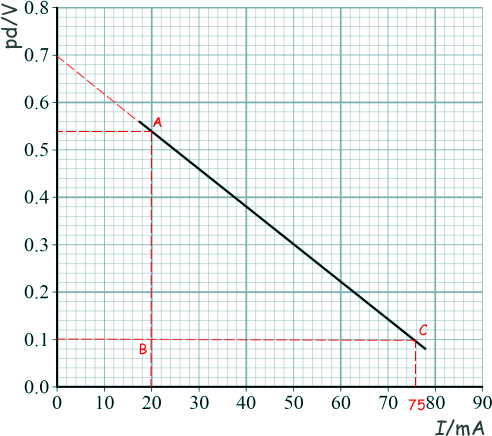
Practical electricity experiment questions

Q2.

(a) An engineer wants to use solar cells to provide energy for a filament lamp in a road sign.

The engineer first investigates the emf and internal resistance of a solar cell under typical operating conditions. She determines how the potential difference across the solar cell varies with current.

The results are shown in the graph in below:

(i) The engineer used the graph to deduce that when operating in typical conditions a single solar cell produces an emf of 0.70 V and has an internal resistance of 8 Ω.

Explain how she used the graph to obtain the values for the emf and internal resistance of the solar cell.


EMF = I(R + r)

EMF = pd +Ir

The graph is a straight line equation (of the form Y = mx + c) with pd as Y and I as x:

pd = -rI + EMF

The EMF is therefore the intercept on the Y axis

When current is zero pd = 0.70V (see graph). This is the EMF - QED

The internal resistance is the negative value of the gradient of the graph:

AB = 0.54 - 0.10 = 0.44 V

BC = 20 -76 = - 56 mA = - 56 x 10-3 A

gradient = AB/BC

= 0.44/-(56 x 10-3)

-r = -7.9 Ω

therefore r ≈ 8 Ω

[2 marks]

(ii) To operate effectively the lamp in the road sign needs a minimum current of 75 mA.

At this current the resistance of the filament lamp is 6.0 Ω.

The engineer proposes to try the two circuits shown below:

Deduce, using calculations, whether the circuits are suitable for this application.

Circuit A

EMF = 0.70 V

r = 8.0 Ω

R = 6.0 Ω

EMF = I(R + r)

0.70 = I x 14

I = 0.70/14 = 0.050A

Therefore the cell supplies only 50 mA - below the 75 mA required and would not be suitable.

Circuit B

The two in parallel would have an emf of one of them (0.7 V) - but putting two of 0.7V in series doubles the emf (1.4 V).

EMF = 1.4 V - see here for cells in series and in parallel the emf is the same as one.

The internal resistances have to be treated like resistances in a combined parallel and series arrangement. The two in parallel will have the overall resistance of just one (4Ω).... that then gets added to the single one (8Ω)

4 Ω + 8 Ω = 12 Ω

r = 12 Ω - need to work out the overall internal resistance from the arrangement - resistors in series and parallel

R = 6.0 Ω

EMF = I(R + r)

1.4 = I x 18

I = 1.4/18 = 0.078A

Therefore the cell supplies 78 mA - above the 75 mA required and would be suitable.

[4 marks]

(b) Solar cells convert solar energy to useful electrical energy in the road sign with an efficiency of 4.0%. The solar-cell supply used by the engineer has a total surface area of 32 cm2 .

Calculate the minimum intensity, in W m–2 , of the sunlight needed to provide the minimum current of 75 mA to the road sign when it has a resistance of 6.0 Ω.

Power needed to run the sign

P = IV = I2R

P = (75 x 10-3)2 x 6.0

P = 0.0338 W

But this is only 4% of the power that has to be supplied to it -

Power needed = 100 x 0.0338/4 = 0.844 W

Intensity = power/area

= 0.844/(32 x 10-4)

264 W/m2

[3 marks]

(Total 9 marks)