Thermistor Questions
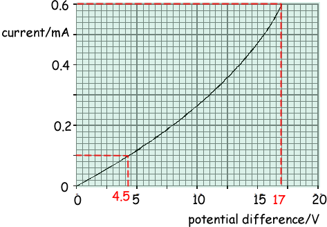
Q1. The graph shows how the current through a thermistor varies with the potential difference across it.

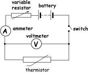
(a) Draw the circuit of an experimental arrangement which could be used to collect the data necessary to produce this graph. On your circuit diagram label clearly a component which would enable the current to be changed continuously across the range.
Circuit diagram to show:

- ammeter in series with thermistor, which must have correct symbol

- voltmeter across thermistor

- variable resistor/variable power supply/potentiometer in series with thermistor

- variable component labelled

(4 marks)
(b)
(i) Using information obtained from the graph, calculate the resistances of the thermistor when the current is 0.10 mA and also when the current is 0.60 mA.
V = IR so R = V/I
resistance (when I = 0.1 mA) = V/I = (45/0.1 x 10-3) = 45 × 103 Ω 
resistance (when I = 0.6 mA) = V/I = (17/0.6 x 10-3) = 28 × 103 Ω 
(ii) Using the results of part (b) (i) deduce how the resistance of the thermistor changes as its temperature increases.
The calculations show that resistance decreases with increasing current 
As the current flow increases through the thermistor it will increase in temperature as the current flow will produce heat energy in the component.  We can therefore deduce that the resistance of the thermistor decreases as temperature increases
(5 marks)
(Total 9 marks)


